-->
≡
Home
Woman
Sport
Business
Health
Privacy Policy
Contact Us
Contact Us
InnovaSonic 207i Ultrasonic Flow Meter: How to Install & Operate
:
:
2017-05-09T21:02:18Z
Tuesday, 9 May 2017 - 09:02 PM
(rhythmic dramatic music)
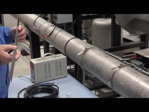
- Hi, I'm Rory Ross with Sierra Instruments.
Today, I'm gonna show you the 207i UltraSonic Flowmeter.
I currently have it set up on a six-inch pipe.
And that's going to be measuring flow
in cubic feet per minute
and it'll be totalizing in cubic feet also.
And, I have the transducer already pre-installed
on a 6-inch line on our calibration facility
here at Sierra Instruments.
There's going to be an upstream transducer,
which is indicated by a red heat shrink,
and then there's a down stream transducer
that's marked with blue heat shrink.
Currently, I have this mounted in the V configuration.
That means the sounds waves as they leave the one transducer
and return to the other transducer
form kind of a V.
It's called two passes, or normally,
people call it a V configuration.
What tools will you need?
You'll need screwdrivers, nut drivers,
and some hardware to mount the enclosure.
The unit will ship with ultrasonic compound, two tubes.
And, as far as special tools that's about all you'll need.
As far as safety concerns, using an AC powered unit,
just follow all the NEC codes and regulations
when it's on AC power.
Every 207i will come with an ultrasonic part.
You'll see it's connected to the upstream transducer
indicated by the red heat shrink.
The blue heat shrink indicates the downstream transducer.
And, you're connected to these two connections.
You'll notice that the 207i is built on a main motherboard.
And often modules in the ultrasonic board
are all plug-in modules on this board.
Options like current input modules,
PT100 sensor modules, and all this are field installable.
Or, if you order it that way, we'll install those for you.
It has a LCD and pretty much a full keypad
with dual-function keys.
Quick keys that will take you to particular menus.
The first thing you need to decide
is where you want to mount the unit.
You want the transducers away from any elbows
and anything that is gonna cause turbulence.
In order to find out the transducer spacing,
you're going to need to power the unit.
Okay, first thing you need to do is mount the enclosed tube
to some suitable place.
You see where I mounted this on this vertical utility box.
It mounts it with four screws.
And, then I'm going to go to the quick installment.
This is where you'll set up the meter and find out,
first, thing you'll need to know,
you'll need to know the spacing;
so, you'll know where to mount the transducers.
And the first thing you'll need to know
is go to the quick start menu and
then you're going to hit enter.
(machine beeps)
Hopefully, you know the outside diameter of the pipe.
If not, you can get a pipe wrap to wrap the pipe
and measure the outside diameter that way.
As far as the pipe outside diameter and wall thickness,
you can get those off the internet on pipe charts.
The closer you can get that, the more accurate you
can get that, the better.
We've actually been using ultrasonic thickness gauge
in the field, ourselves.
They're not that expensive, and if you install a lot
of these, probably not a bad investment.
And the pipe outer diameter on this particular pipe
is 6.65 inches.
You'll type that in. (machine beeps)
The wall thickness, you'll type that in also.
This particular pipe is .258.
Press enter. (machine beeps)
This is a carbon steel pipe. (machine beeps)
There's no liner.
This is like for mortar-lined pipes and things.
(machine beeps)
Fluid is simply water. (machine beeps)
And, we're running calibration on this so we've
got the temperature, fluid temperature,
very accurately entered.
Default 68 degrees. (machine beeps)
Okay, I think you're going to pick up the trend.
Select the transducers type.
We're using the standard transducers.
(machine beeps)
And then we are using the V configuration
that I talked about before.
(machine beeps)
Now, it's reading this mem key that stores
the parameters for this transducer.
This graph is showing you
the return signal from the transducer.
Okay, as you're attaching the transducers,
you're going to need to verify that you actually
have the spacing correct.
If all your pipe dimensions are correct
and you've got it set to the exact spacing up here,
you will a T-O-M, T-O-S very close to 100%
like I did here.
Sometimes, there's going to be...
You're really not going to know the exact dimensions
of the pipe and the temperature of the water;
so, you're going to end up with 99 or 101.
That's fine.
Here I have it perfect.
What you're shooting for is this line and the beginning
of this wave form should be between these two,
what they're calling goal posts.
That's telling you that the transducer's actually
in the proper location.
If the spacing is wrong, say likes it's too far apart,
this wave form and line will be outside of this window.
If it's too close together, this wave form
will be over here towards the edge.
And your location should be away from any elbows.
The flow direction is this direction on this pipe.
Now, that you can see the spacing we need,
you know it's going to be 4.93 inches.
You're ready to draw a straight line
across the center line of the pipe.
And then, you're going to put a notch on the pipe
with a marker at about the same spacing
that it was told you in the spacing menu.
In this case 4.93 inches.
Okay, first thing you're going to need to do is put
a good coating of silicone grease that comes
with these units on your transducer.
Mostly, you are concerned with the little orange area.
That's where sound waves are going to come out.
This couples the sound waves to the pipe.
Then, you're gonna to clamp on your transducers.
And you pre-tighten your clamp.
You can kinda do this by yourself.
The silicone grease should kind of squish out on the bottom.
I'm going to do the upstream transducer
doing the same thing.
Going to slide this over, then I have close clamp
kind of pre-tensioned, which makes it a little easier
to install by yourself.
Okay, cinch it up.
Don't worry about getting this down
to the the thousandths of an inch.
It's not that critical.
So, as you can see, I've got the spacing right on.
T-O-M, T-O-S is 100%, which is perfect.
Now, let's go ahead and we can watch flow
in the flow net menu.
This is one of the quick menus here.
When you hit that these are all single button touch menus.
It's going to start up again.
Okay, there's the flow rate in the top line,
and the net total in the second line.
Okay, everything I talked about on the quick installment
you can also be configured in an app
for the 207i that comes with the unit.
Simply plug into the USB port provided,
and the other end of the USB port
will got to your laptop computer.
Right now, I'm going to talk about using
the 207i and energy applications.
You already have a flowing liquid, water in this case.
It has a specific heat; so, the only thing you need
in the equation now is the temperature difference
between the water going into the heat exchanger
and the water coming out.
To do that, there's two ways of getting
the temperature data in here.
There's current input board modules.
You can power temperature transmitters.
They are set up as passive or active;
so, you can power a loop power device with just two wires.
If you buy it as a package,
you can order temperature transducers.
We have two styles.
These are PT100 style or TDs.
This particular unit straps onto
the top of the pipe, like this,
with two pipe straps to hold it in place.
It's not optimum because it is outside of the pipe.
The best type of a transducer is an insertion type.
And, this is basically the same R-T-V, PT100, cell R-T-V.
With this one, you're going to need
to cut a half inch normal pipe thread
on the left and insert it in the pipe.
Normally, you're going to need two R-T-Vs.
These are PT100s again.
One's gonna go upstream on your chiller line,
and the other is gonna go downstream on your return line.
The most important measurement is not the absolute
temperature of the liquid but the difference
between the two.
That's in the formula for calculating BTU energy.
I can't over stress the importance of your measuring
the difference not the absolute temperature.
And, also, when you order these as a set,
we'll calibrate these as a system
and calibrate 'em with the 207i
with the matched PT100 boards, and zero these out;
so, they actually will measure that difference.
I'm going to go the flow net menu.
(machine beeps)
And, it's showing me right now I have zero flow in the pipe.
Okay, Joe, go head and hit enter.
And, now we are going to crank up the flow test loop.
And, you'll see the flow's increasing.
That's measuring the flow inside the pipe.
And, it's getting there.
All right.
There we are.
You've got connected to the pipe,
we didn't have to drill any holes into the system.
And, we're measuring flow.
It's matching the standard very closely.
Hope you enjoy using this amazing product.
We'll see you again here at Sierra Instruments.
Bye.
Facebook
Twitter
Google Plus
Sierra Instruments Inc
Latest Posts